Clamp Filters
Reducing Emission Noise from Cables
Even when an electronic device is designed with noise considerations in mind—such as carefully placing components, using proper grounding, and including filtering on the PCB—it may still generate or be susceptible to high levels of noise when connected via an interface cable. Cables, with their long length and large surface area, are particularly prone to radiating or receiving significant electromagnetic interference.
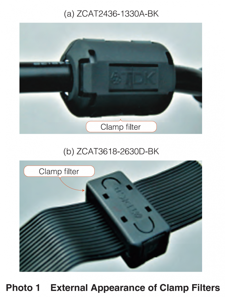
One solution is the use of a clamp filter, as shown in Photo 1. This device consists of two semi-circular ferrite cores housed in a plastic case. It can be easily attached to a cable in a single step without the need to cut the cable, making it particularly useful for addressing noise issues just before shipping a product. Photo 1 (b) depicts a version that can be mounted onto a cable inside a device. Clamp filters come in various sizes to fit different cable diameters.
Understanding Common Mode Filters
Common mode filters (CMFs) are often associated with components mounted directly onto a PCB. However, clamp filters also function as common mode filters. They are designed to suppress common mode noise on interface cables without affecting differential mode currents. Unlike CMFs with wound conductive wires, clamp filters have minimal stray capacitance or electromagnetic coupling. This means that differential mode impedance remains low across a broad frequency range, with minimal impact on signal quality. Clamp filters generally maintain stable impedance characteristics up to around 1 GHz due to the absence of stray capacitance effects.
Optimizing Winding Amount
Increasing the number of turns of a cable around a clamp filter improves impedance and enhances noise attenuation. However, more windings also increase stray capacitance and electromagnetic coupling. The optimal number of windings can be determined through experimentation.
1. Confirming the Effect of Reducing Emission Noise through Experiments
In addition to AC power adapters, various peripheral devices, such as digital still cameras or mobile phones, are connected to mobile terminals represented by mobile PCs through various interface cables. In this section, clamp filters will be mounted to these interface cables and their noise reduction effects will be tested.
Connecting an AC Power
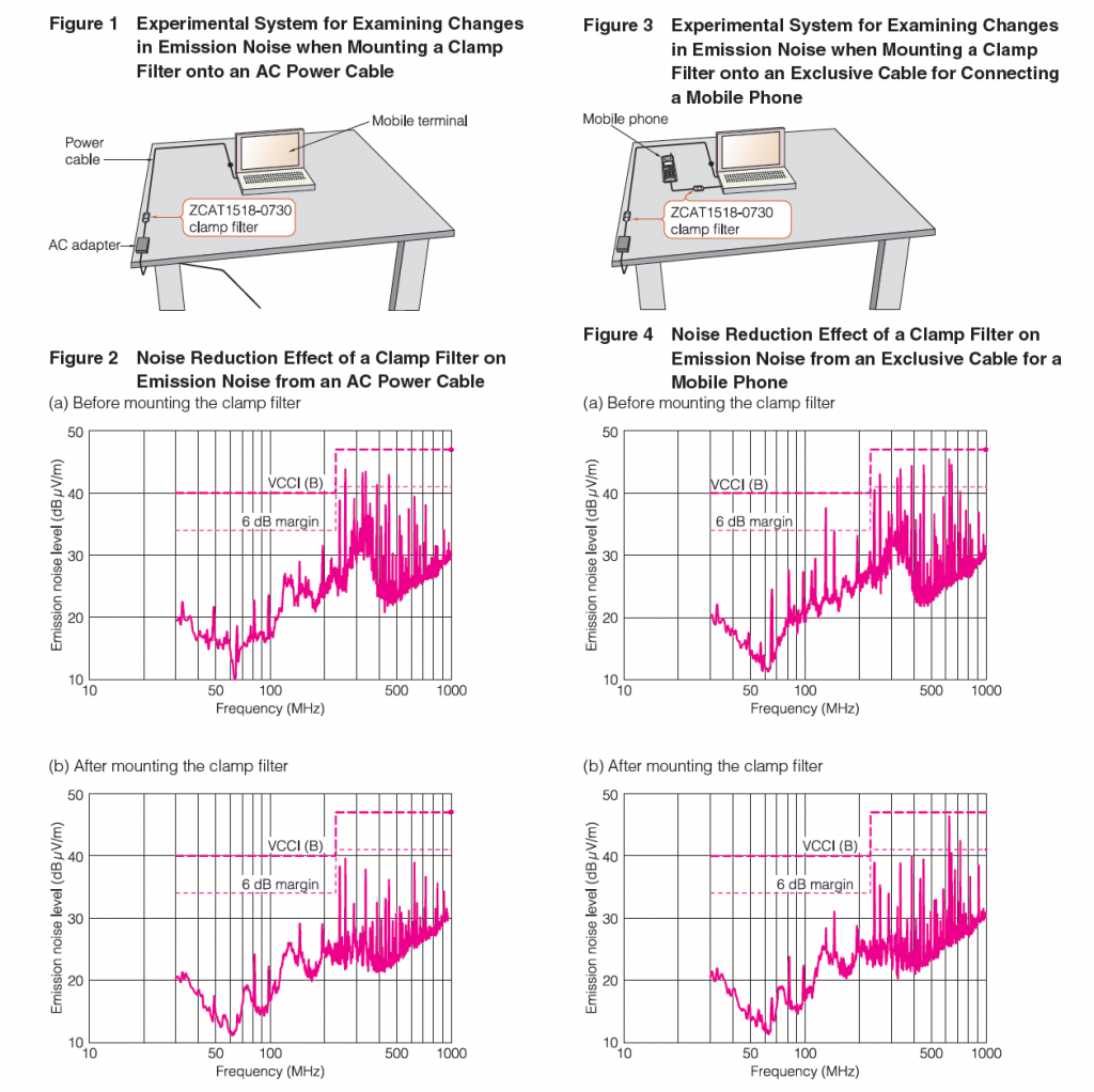
The spectrum of emission noise from a mobile phone before and after mounting a ZCAT1518-0730 clamp filter to the power cable is shown in Figure 1. In this test, a cable was wound twice around the filter. The measurement results are shown in Figure 2. Before mounting, noise was emitted at frequencies from 250 to 600 MHz, barely satisfying the VCCI class B standard. After mounting the clamp filter, noise was relatively reduced by approximately 5 to 10 dB.
Connecting a Mobile
As is shown in Figure 3, a mobile terminal was connected to a mobile phone with an exclusive cable, with a ZCAT1518-0730 clamp filter connected to the power cable.
The measurement results are shown in Figure 4. Before mounting the clamp filter, noise was emitted at a broad frequency band from 100 to 600 MHz. As in the case of the previous test, after winding the exclusive cable twice around the clamp filter, noise was relatively reduced by 5 to 10 dB. Noise at frequencies of 600 MHz or higher, which did not change after mounting the clamp filter, seemed to be emitted from sources other than the cable.
2. Clamp Filters Improve Immunity to Electrostatic
When a clamp filter is installed, it not only reduces emission noise but also minimizes errors caused by external noise, such as surges or static electricity. To assess the impact of the clamp filter on error frequency and severity, an ESD (electrostatic discharge) immunity test was conducted in accordance with the IEC61000-4 international standard.
ESD occurs when an electric charge builds up on a body, such as from friction with clothing, and is discharged when the body contacts an electronic device. Immunity refers to a device's resistance to external noise.
Testing Method
As illustrated in Figure 5, a functioning mobile terminal was connected to a printer. Static electricity was discharged onto the mobile terminal, and the resulting errors were tracked. ESD was applied to the connector plug shell on the mobile terminal side of the cable 10 times at one-second intervals.
The discharge followed the contact discharge method outlined in IEC61000-4-2. The electrostatic pulse waveform used for testing, as specified by the standard, is shown in Figure 6. The test levels were set at 2 kV, 4 kV, and 6 kV.
Test Results
The results are summarized in Table 1. Without the clamp filter, errors such as the printer stopping occurred at 4 kV, and at 6 kV, the printer completely ceased operation. When one ZCAT2035-0930A clamp filter (with a single winding) was used, operations continued without issues at 4 kV, and only minor errors occurred at 6 kV. When two windings were applied, no errors were observed at any voltage level.
3. ESD Noise Suppression Effects in a Parallel Two-Wire Line
The ESD noise suppression effect of a clamp filter when it is mounted onto a parallel two-wire line was evaluated by an experiment. A comparison was made with the previously-described onboard type CMF.
Measurement System
The measurement system is shown in Figure 8. Two parallel wires with a length of 1 m were placed at a height of 0.1 m from the ground plane. 6 kV of static electricity generated by an electrostatic generator was applied by an ESD gun to the input side of the line. The ESD and the line were brought into contact with each other. The waveform of static electricity generated by the electrostatic generator was a high speed, spike voltage with a rise time of between 0.7 to 1 ns.
A ZCAT2035-0930A clamp filter (hereinafter referred to as ZCAT) and a onboard type CMF ZJYS51R5-2P (hereinafter referred to as ZJYS) were inserted into the halfway point of the parallel wires, and changes in the ESD waveform were observed on the output side. As is shown in Figure 9, two types of PCBs were prepared onto which ZJYSs were mounted; one was a PCB with a thickness of 1 mm, having no copper foil pattern on the back side (PCB), and the other was a PCB with a thickness of 0.3 mm, with the entire backside being a ground plane (PCB).
High Surge Noise Suppression Effect
The waveforms observed at the output terminal are shown in Figure 10.
From Figure 10 (a), it is clear that approximately 40% of noise was attenuated after the clamp filter was mounted. Ringing immediately following the voltage rise was also attenuated.
In Figs. 10 (b) and (c), the waveforms in the cases where ZJYSs were mounted show that ringing was attenuated to the same extent as ZCATs, but that the spike voltage at the rise time was not attenuated. In particular, there was almost no attenuation in the PCB [A]. In order to examine the cause, the input/output capacitances of the PCB [A] and PCB [B] were measured using a capacitance meter. As a result, the capacitance of the PCB [A] was approximately 0.1 pF and the capacitance of PCB [B] was 7.3 pF. It seems that in the PCB [B], large stray capacitance existed between the copper foil on the component surfaces and that electrostatic noise escaped to the output side through this capacitance, as is shown in Figure 11. As a reference, the impedance frequency characteristics of the clamp filter, the PCB [A] and PCB [B], which were used for the experiments, are shown in Figure 12.
From these experimental results, it is clear that clamp filters exhibit higher surge voltage suppression effects than onboard type CMFs. This is because their ferrite cores do not easily become saturated even when high surge voltage is applied, due to their large physical capacities. Since they are not mounted onto PCB boards, it is not necessary to take into consideration capacitance coupling between inputs and outputs.

